Overview:
Author: Diyaa
Published date: August 9th, 2024
Last updated: August 10th, 2024
This article contains all of my personal knowledge that I learned about routing while serving my time in post-secondary education.
About Me:
My name is Diyaa. I graduated from a network engineering post secondary program in 2023. I like to spend majority of my personal time making network infrastructure diagrams and technical documentation like the article you are reading right now. I am able to make large scale networks at home thanks to Proxmox virtual environment.
Link to original
Introduction to Routing:
Mermaid graph of the OSI module:
graph TD;
  Application["Application Layer (Layer 7) - QUIC, HTTPS, DNS, FTP SSH"]
  Presentation["Presentation Layer (Layer 6)"]
  Session["Session Layer (Layer 5)"]
  Transport["Transport Layer (Layer 4) - TCP, UDP, ICMP, SCTP"]
  Network["Network Layer (Layer 3) - IPv4, IPv6"]
  Data_Link["Data Link Layer (Layer 2) - Ethernet"]
  Physical["Physical Layer (Layer 1) - Physical cable"]
  Application --- Presentation
  Presentation --- Session
  Session --- Transport
  Transport --- Network
  Network --- Data_Link
  Data_Link --- Physical
TCP/IP networks routing is the process of sharing routes in between computer networks. A broadcast domain (layer 2) Local Area Network (LAN) segment can not cross into another broadcast domain segment without the routing of unique network layer address ranges. Routing operates at layer 3 of the OSI module (This layer is known as the network layer) to help scale networks beyond the boundaries of the data link layer.
Static Routing:
Static routing is the process of adding routes manually to each router to advertise routes in between routers. Static routing will provide the most performance and the lowest overhead since the router does not need to send dynamic advertisements periodically as the case with dynamic routing. However, static routes can become hard to manage as networks grow and scale.
Static routes will always have a higher administrative distance and route preference over dynamic routes on every vendor equipment out there.
Dynamic Routing Protocols Types:
There are different types of routing protocols for routing TCP/IP networks. Some of the most famous routing protocols are:
- Distance vector: “Routing by Rumor”.
- Link state: “Routing by road map”.
- Path vector: Routing by autonomous system path.
Distance Vector Routing Protocols:
Distance vector routing protocols determine the best dynamic route between the source and destination based on the distance (number of hops or routers). For example, distance vector routing protocols like RIP have a hop limit of 15. However, advanced distance vector routing protocols like EIGRP do not rely on the hop count as the route preference making them scale beyond the 15 hop limit.
Example
Note
EIGRP is more advanced than RIP. Therefore, you may hear some network administrators refer to it as an advanced distance vector routing protocol.
Here are some examples of distance vector routing protocols:
- RIPv1
- RIPv2
- EIGRP
Link State Routing Protocols:
Link state routing protocols are more advanced than distance vector routing protocols. They build a map of the entire network knowing exactly how far away each network lives based on the route preference. The Open Shortest Path First (OSPF) routing protocol uses the bandwidth to determine the best route.
Link state routers advertise their links making them more trust worthy than most distance vector routing protocols. OSPF is the most famous open standard link state routing protocol that can scale to manage and link networks.
I personally like link state routing protocols due to their ability to scale. I use OSPFv2 (IPv4 routing) and OSPFv3 (IPv6 routing) within my home network to maintain a dynamic and redundant network. I think of OSPF as the most shiny glowing star in the galaxy of link-state routing.
Example
Here are some examples of link state routing protocols:
- OSPFv2 and OSPFv3.
- IS-IS.
Path vector:
Path vector routing protocols record the number of every autonomous system in the path from the source AS to the destination AS. This is why they are referred to as path vector rather than distance vector.
Note
Even though iBGP operates within a single autonomous system, it is still classified as a path vector routing protocol since it has the path of the AS as one of it’s route attributes.
Example
Here are some examples of path vector routing protocols:
- iBGP.
- eBGP
Autonomous Systems (ASNs):
An autonomous system (ASN) can be described as a group of routers that belong to a single routing domain. Basically, an organization that maintains their own internal network runs a single autonomous system network.
You can think of each house on your street as an autonomous system. Inside of each house there may be a single or multiple household(s) (those are the routers within an AS). They share a single building to live in which classifies as a “single living space”. The neighboring houses can be seen as external autonomous systems. It is the same exact concept when it comes to routing.
Interior Gateway Routing Protocols (IGP):
Interior Gateway Protocols (IGP) are routing protocols that run within a single autonomous system. They manage all the networks within a single organization’s routing domain.
Example
Here are some examples of IGP routing protocols:
- iBGP.
- RIPv1.
- RIPv2.
- EIGRP.
- OSPFv2.
- OSPFv3.
- IS-IS.
The most famous IGP routing protocol in North America is OSPF. However, IS-IS may be more famous in other parts of the world.
Exterior Gateway Routing Protocols (EGP):
Exterior Gateway Protocols (EGP) are routing protocols that run in between different autonomous systems. They allow the sharing of routing information across different autonomous systems.
Example
Here are some examples of EGP routing protocols:
- eBGP.
Administrative Distance (AD):
The administrative distance is the trust worthiness of a routing protocol. The lower the administrative distance, the more trustworthy the routing protocol.
Note
This table below presents the default administrative distance values for Cisco IOS. Other vendors might choose to implement AD with different values.
| Routing source | Administrative distance | Comments |
|---|---|---|
| Directly connected (IP on the interface) | 0 | |
| Static route | 1 | |
| eBGP | 20 | |
| EIGRP (Internal) | 90 | |
| IGRP | 100 | Rare to see IGRP these days. |
| OSPF | 110 | |
| IS-IS | 115 | |
| EGP (Exterior Gateway Protocol) | 140 | You might be over 50 years old if you have seen this in your life span. |
| RIP | 120 | |
| EIGRP (External) | 170 | |
| iBGP | 200 | |
| DHCP learned routes | 254 | |
| Unknown/Untrusted | 255 |
IP Address allocation:
A network layer Protocol Data Unit (PDU) contains IP addresses to allow TCP/IP networks to expand beyond the horizon of the data link layer (layer 2 of the OSI module). Imagine an internet with layer 2 only? It is simply not possible. Therefore, the network layer is what allows the internet to scale.
The most famous network layer protocols that are heavily used in today’s networks are IPv4 and IPv6.
Public IPs and BGP ASNs allocation:
Reference for this section:
footnote
packetpushers-01under the References section at the bottom of the page 1.
Public IP address are network ranges that are routable over the public internet. IPv4 or IPv6 packets with these addresses in the source and/or destination will not be filtered (dropped) by Internet Service Providers (ISPs.)
Internet Assigned Numbers Authority (IANA) is responsible for the coordination of the internet standards and number assignments. IANA is responsible for the following tasks:
- Global pool of IPv4/IPv6 addresses and block allocations for each region (network layer addresses).
- Protocol number assignment (protocol identification numbers).
- Port numbers assignment (transport layer addresses).
- DNS root zones.
The screenshot below shows the Regional Internet Registry (RIR) organizations that are responsible for the allocation of public IPv4, IPv6 addresses, as well as public BGP Autonomous System Numbers (ASNs) within their perspective region.
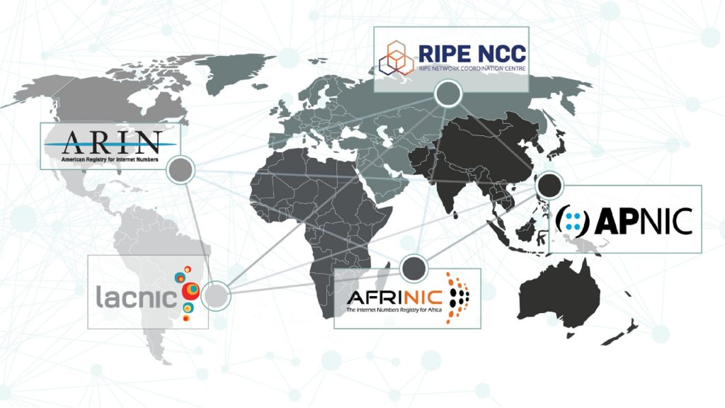
- American Registry for Internet Numbers (ARIN).
- Reseaux IP Européens Network Coordination Centre (RIPE NCC).
- Asia-Pacific Network Information Centre (APNIC).
- Latin American and Caribbean Network Information Centre (LACNIC).
- African Network Information Centre (AFRINIC).
Special Use IPs allocation:
Note
Special use IP address are network ranges that may not be routable over the public internet.
IPv4 Special Use Addresses:
Note
Those are ranges that I have used safely within an internal network. There are more, but I can’t confirm if they are safe to use internally.
| Network Range | RFC | description |
|---|---|---|
| 192.168.0.0/16 | RFC1918 4 | Private IP range for internal use. |
| 172.16.0.0/12 | RFC1918 4 | Private IP range for internal use. |
| 10.0.0.0/24 | RFC1918 4 | Private IP range for internal use. |
| 127.0.0.0/8 | RFC1122 5 | loopback IPv4 range (this range is non-routable.) |
| 169.254.0.0/16 | RFC3927 6 | Dynamic link local IPv4 addresses. This range is also known as APIPA. |
| 192.0.2.0/24 | RFC5737 7 | Network documentation IPv4 address range. |
| 198.51.100.0/24 | RFC5737 7 | Network documentation IPv4 address range. |
| 203.0.113.0/24 | RFC5737 7 | Network documentation IPv4 address range. |
| 198.18.0.0/15 | RFC2544 8 | Benchmarking network testing range. |
| 100.64.0.0/10 | RFC6888 9 | Carrier Grade Network Address Translation (CGNAT) range. |
IPv6 Special Use Addresses:
Note
Those are ranges that I have used safely within an internal network. There are more, but I can’t confirm if they are safe to use internally.
| Network Range | RFC | description |
|---|---|---|
| ::1/128 | RFC4291 10 | Loobpack IPv6 address (this range is non-routable.) |
| ::/128 | RFC4291 10 | Unspecified IPv6 address (this range is non-routable.) |
| fe80::/10 | RFC4291 10 | Link-local IPv6 range (this range is non-routable.) |
| fc00::/7 | RFC4193 11 | Unique Local addresses (ULA). The RFC1918 of IPv6. |
| 2001:db8::/32 | RFC3849 12 | documentation IPv6 range. |
A Technical Explanation of Packet Switching Interface Routing:
Have you ever wondered how packets get forwarded at layer 3? In this section, I will explain how unicast IPv4 traffic gets forwarded.
Note
This process is very similar for IPv6 routing. However, the only difference is that IPv6 uses the Neighbor Discovery Protocol (NDP) within ICMPv6 while IPv4 uses the Address Resolution Protocol (ARP) at layer 2 for MAC address discovery. You will sometimes hear network administrators refer to ARP as layer 2.5 as a joke.
Diagram:
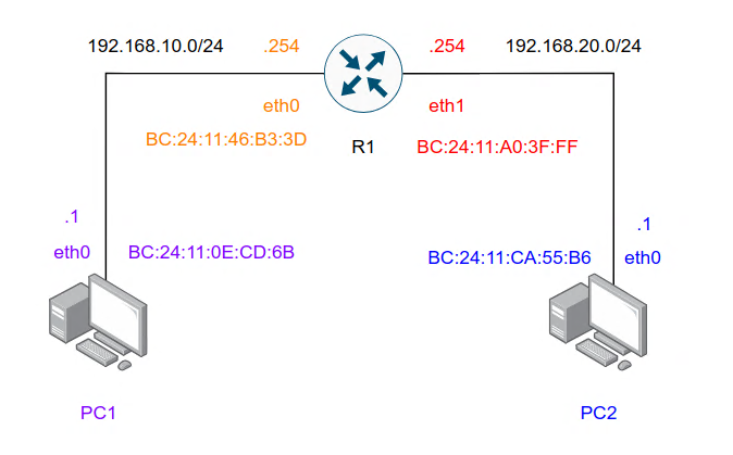
Here is a diagram of what I am about to demonstrate in this section.
Technical explanation:
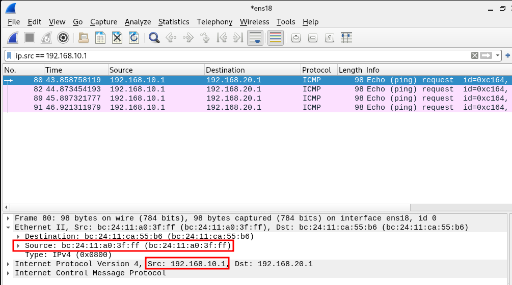
I have sent multiple ICMP echo-requests from PC1. The packets have the source IPv4 address of 192.168.10.1 (PC1) and the destination IPv4 address of 192.168.20.1 (PC2). The networks for both LAN segments are /24 networks (dotted decimal subnet mask of 255.255.255.0). Both of these networks reside in a different broadcast domain (layer 2 LAN segment) which makes layer 3 routing the best way of linking them.
Packets Forwarded to R1 from PC1:
Notice in the screenshot below how the destination MAC address for the ICMP echo-request packet from PC1 is set to BC:24:11:46:B3:3D? Isn’t that the Router’s MAC address on interface eth0? That is the exact reason to why you have to define a default gateway on an end-host operating system (server, workstation, etc.) If the network that the host is trying to reach does not reside in the same broadcast domain, the host will set the destination MAC address of the packet to be the default gateway’s MAC address.
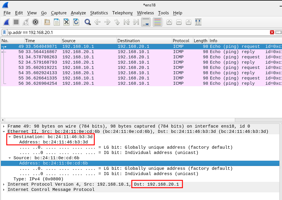
This is what is known as packet switching. Packet switching is the process of taking a packet from one interface and forwarding it out another interface. When routing is done at a larger scale, routers take packets from a network that end-hosts reside in (workstations, servers, etc… any device that is incapable of routing.) and forward it out another interface where a router resides. All that is happening is that the layer 2 frame is being replaced at every hop as the packet gets forwarded in between routers.
Note
I am not referring to the ARPANET age packet switching technology that was introduced to replace circuit switching. I am referring to packet switching as the process/concept of how packets get forwarded in modern day TCP/IP networks.
Router Making Routing Decision:
The router will make a routing decisions based on the routes in it’s routing table. The router in this case has “directly connected” routes for the 192.168.10.0/24 and 192.168.20.0/24. That will result in the router performing packet switching from one interface to another interface.
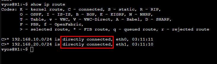
If there are multiple routing protocols in the routing table of this router it would have to follow the Administrative Distance (AD) and the route preference value in the route table to determine the best route.
Packets Forwarded to PC2 from R1:
Here is the packet as it exits the router’s eth1 interface and get forwarded to PC2. You will notice that the source MAC address of the packet from host PC1 IP address is showing as the router’s MAC address. This is literally what happens in your home network every single millisecond.
I had an instructor in college named Terry Pearce, who taught TCP/IP network functionality in the most detailed way possible. This is why I understand this and I am able to demonstrate it.
Related Notes:
References:
- Book: CCIE Professional Development Routing TCP/IP Volume I, Second Edition by Jeff Doyle.
- Book: CCIE Professional Development Routing TCP/IP Volume II, Second Edition by Jeff Doyle.
- Book: CCNA 200-301 Portable Command Guide, Fifth Edition by Scott Empson.
- Instructor notes (from the network engineering technology program at NAIT): Terry Pearce.
- Instructor notes (from the network engineering technology program at NAIT): Monica Ciobanu.
- Kevin Wallace training videos on YouTube.
- Keith Barker training videos on YouTube.
- Articles and podcasts on packetpushers.net.